Finite Impulse Response
🎯 Learning Objectives
By the end of this topic, you should be able to:
- Understand why the impulse signal contains all possible frequencies.
- Explain why FIR filters have a finite-duration impulse response.
- Recognize that FIR filter coefficients and impulse response values are the same.
- Describe why FIR filters are inherently stable.
- Interpret how the frequency response of an FIR filter is related to its impulse response.
- Understand the concept of FIR filter design using the inverse FFT method.
Recap of Previous Topics:
In the earlier sections, we explored feedforward filters and tested them using signals of various frequencies:
- 0 Hz (DC)
- Nyquist Frequency
- Half Nyquist Frequency
- Quarter Nyquist Frequency
The last type of test signal we analyze is the Impulse Signal, which is critical in digital signal processing.
Impulse Signal Properties:
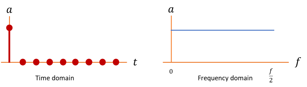
The Impulse Signal has a very special property:
- It contains all frequencies from 0 Hz up to the Nyquist frequency.
- This means it can excite every part of the filter’s frequency spectrum.
Visually, it looks like a single spike at the start
Now that we have a better understanding of what an Impulse signal is, let us pass it through the filter and get an Impulse response. Below is the animation about it.
Key Observations About FIR Filters:
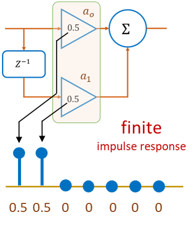
- Impulse Response = Filter Coefficients
- In feedforward filters, the non-zero values of the impulse response exactly match the filter coefficients.
- Example: If the filter has coefficients a0 and a1, the impulse response will contain these two values directly.
- Time Domain Shape
- The impulse input gets “flattened” and smeared according to the coefficients.
- With two taps, it might look like two spikes, resembling a tiny sinc-like shape.
Exercise:
Let us look at programmatic examples of this. We run python on jupyter notebooks and you can do this exercise in Python Sandbox below
Press Run Code: Output will appear here.
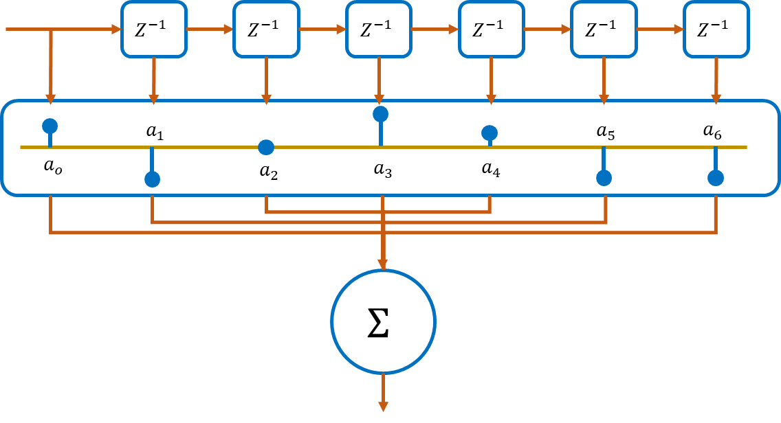
However, the filters with only two taps like we have seen is not very useful.
To get a more customized frequency response from our filter we need several tabs sometimes hundreds.
The idea is incredibly simple the coefficients of each of the tabs represent the impulse response of the filter.
So a non-mathematical approach of designing an FIR filter would be the first design the frequency response that we are looking for then perform an inverse .
This will basically convert the signal from the frequency domain to the time domain.
The result would be an impulse response whose sample values can be mapped as coefficients of the filter.
🎨 Interactive Test Signal & Filter Demo
FIR Filter Impulse Response Demo
Input Signal
Filtered Output
FIR Frequency Response (Magnitude)
🧠 Key Takeaways
- Passing an impulse into a filter reveals all frequencies at once, making it the perfect test signal.
- A feedforward filter produces only a finite number of non-zero output samples, hence the name Finite Impulse Response (FIR).
- For any FIR filter, the impulse response is identical to the filter coefficients.
- FIR filters are always stable, because their output dies out after a finite number of samples.
- Increasing the number of FIR taps allows more precise control over the filter's frequency response.
- Designing an FIR filter can be viewed as: choose desired frequency response → inverse FFT → obtain impulse response → use it as coefficients.
🧠 Quick Quiz
Test your understanding of feedforward filters:
1) Why is the impulse signal used to analyze filters?
2) What is special about the impulse response of an FIR filter?
3) What are the non-zero values of an FIR filter’s impulse response equal to?
4) Why are FIR filters always stable?
5) How can you design an FIR filter using the frequency domain?